
Achieving a genuinely accessible open-plan layout is not about demolition; it’s a precise engineering exercise in creating seamless, barrier-free pathways for life.
- Success lies in mastering details like flush thresholds, effective door widths, and guaranteed circulation space, not just removing walls.
- Anticipatory design, considering future mobility needs from the outset, prevents costly and disruptive retrofitting later.
Recommendation: Engage a structural engineer at the concept stage to integrate these critical lifetime-living principles into your architectural plans, ensuring compliance and true future-proofing.
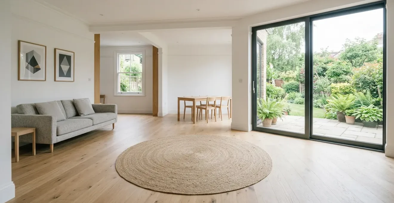
The vision of a light-filled, open-plan ground floor is a common aspiration for owners of UK semi-detached homes. The dream is one of fluid family living, enhanced social space, and a connection to the garden. The typical approach often starts and ends with a single, dramatic act: knocking down the wall between the kitchen and dining room. While this creates an illusion of space, it often fails to address a more profound, long-term requirement: creating a home that remains functional, safe, and dignified through every stage of life.
This isn’t merely about interior design or accommodating a temporary injury; it’s about visionary home adaptation. The conventional focus on aesthetics overlooks the critical engineering details that enable genuine lifetime living. Issues like subtle changes in floor level, the intrusive arc of a door hinge, or the placement of a simple plug socket can transform a seemingly open space into an obstacle course for anyone with reduced mobility, whether a parent with a pushchair, an elderly relative, or a wheelchair user. The difference between a fashionable open space and a truly functional one is measured in millimetres.
This guide moves beyond the sledgehammer. As a structural engineer, my perspective is that true open-plan design is an exercise in foresight and precision. We will deconstruct the specific technical challenges and solutions required to transform a standard UK semi-detached ground floor into a genuinely accessible, compliant, and beautiful environment. We will explore the science behind circulation space, the legal frameworks governing adaptations, and the subtle yet crucial details that deliver a seamless experience for every occupant, today and for decades to come.
To navigate this complex but rewarding process, this article breaks down the essential engineering and design considerations. From the foundational principles of wheelchair accessibility to the specific challenges of adapting period properties, each section provides the technical insight needed to plan your renovation with confidence.
Summary: An Engineer’s Guide to Future-Proof Open-Plan Living
- Why do you need a 1500mm turning circle for future wheelchair access?
- How to get Part M compliance signed off for your extension?
- Flush thresholds vs ramped strips: achieving a seamless flow between rooms
- The mistake of widening the door frame but forgetting the knuckle of the hinge
- Where to position plug sockets so you don’t have to bend down?
- When to replace your bathroom suite: 3 signs your current setup is becoming dangerous
- Why can’t you put a ramp on a public pavement without council permission?
- How to adapt a Victorian terraced entrance with steep steps for a rollator?
Why Do You Need a 1500mm Turning Circle for Future Wheelchair Access?
The requirement for a 1500mm turning circle is the geometric foundation of accessible design, ensuring a wheelchair user can turn 360 degrees without performing a multi-point turn. This is not an arbitrary number but a carefully defined space that dictates the minimum clear floor area needed in key zones like hallways, kitchens, and open-plan living areas. Without this clear zone, a space is not truly navigable, forcing awkward and often strenuous manoeuvres.
From a structural engineering perspective, achieving this means that « open-plan » is defined by clear, unobstructed floor space, not just the absence of walls. The placement of columns, kitchen islands, or even load-bearing furniture must be planned around protecting this critical circle. For instance, an island placed centrally in a kitchen-diner might look good, but if it encroaches on the turning circle, it compromises the core accessibility of the entire room. We must design load paths and structural supports that create and preserve these zones.
While the regulation provides a baseline, true anticipatory design acknowledges its limitations. The Department for Transport highlights this critical nuance in its guidance on inclusive mobility:
Skilled users of manual wheelchairs can turn through 360° in a space no more than 1500mm x 1500mm, but this is insufficient for larger chairs, particularly outdoor electric wheelchairs (turning circle 2420mm), electric pavement vehicles (turning circle 4350mm) and for wheelchair users with extended leg rests.
– UK Department for Transport, Inclusive Mobility: A Guide to Best Practice on Access to Pedestrian and Transport Infrastructure
This means that while the 1500mm x 1500mm minimum turning space is the legal target for compliance, a visionary design might aim for a more generous 1800mm or 2000mm in high-traffic areas, accommodating a wider range of mobility devices and future-proofing the space more robustly. This is where planning triumphs over simply reacting.
How to Get Part M Compliance Signed Off for Your Extension?
Achieving sign-off for Part M of the UK Building Regulations, which covers « Access to and use of buildings, » is a formal process of verification, not a mere formality. Compliance is demonstrated through physical inspection by a building control officer (from either the local authority or an approved private inspector). Their role is to certify that the built work matches the approved plans and meets all accessibility standards, such as level thresholds, door widths, and socket heights.
The key to a smooth sign-off is embedding Part M requirements into the design from day one and maintaining meticulous site execution. From a structural engineer’s standpoint, this means our drawings and specifications must explicitly detail these features. For example, the foundation design for an extension must be calculated to achieve a finished internal floor level that perfectly matches the main house, facilitating a flush threshold. Any deviation during the build can lead to a non-compliant step that is costly to rectify.
The site inspection is the critical final gate. The inspector will physically measure openings, check gradients, and observe the constructed details against the regulations.
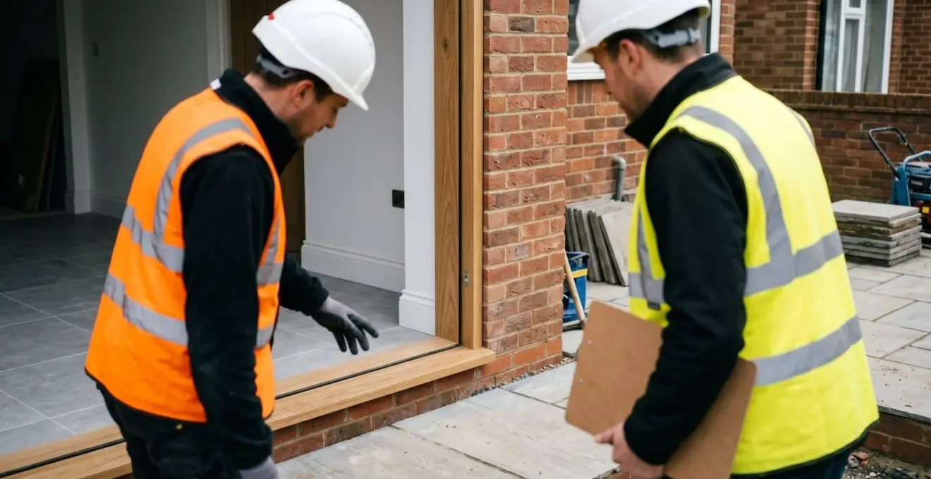
As this image illustrates, the inspection is a moment of truth where design intent meets built reality. The officer is verifying that every detail, like the level threshold at the new doorway, has been constructed correctly. Success here depends on a collaborative effort between the architect, structural engineer, and builder, all working from a shared, compliant design. Clear communication and quality control throughout the construction phase are non-negotiable to prevent a failed inspection, which can delay project completion and incur significant extra costs.
Flush Thresholds vs Ramped Strips: Achieving a Seamless Flow Between Rooms
A truly open-plan space is defined by seamless transitions, and nowhere is this more critical than at the floor level. A raised threshold, even a small one, is a trip hazard and a significant barrier for wheelchair users or those with walkers. While simple ramped transition strips are a common retrofit solution, they are a compromise. The gold standard for new builds and major renovations is the engineered flush threshold, creating a completely uninterrupted floor plane between inside and out, or between two rooms.
Achieving a flush threshold, particularly at an external door in the UK’s wet climate, is a significant technical challenge that requires integrated structural and waterproofing design. It is not simply a matter of levelling the floors. To prevent water ingress, the design must incorporate concealed drainage systems. A comprehensive technical study on this subject details methods like using recessed screeds and integrated linear drainage channels (often called ACO drains) hidden beneath the threshold. This allows any water that breaches the weather seals to be safely collected and drained away, protecting the building’s structure.
Where a completely flush finish isn’t feasible, Building Regulations Part M provides a tolerance. A threshold can have a height, but it must be designed to be as unintrusive as possible. The regulations are very specific, allowing a 15mm maximum height with 5mm chamfered edges to minimise the obstacle. However, this should always be seen as a secondary option. The primary goal in any visionary adaptation is to engineer the floor structure, drainage, and door system to work in concert, eliminating the threshold altogether and delivering a truly seamless and dignified transition for every user.
The Mistake of Widening the Door Frame But Forgetting the Knuckle of the Hinge
A common oversight in accessibility planning is focusing solely on the structural opening of a doorway while ignoring the hardware that occupies it. A standard door, when opened to 90 degrees, has a hinge knuckle that protrudes into the clear space, effectively narrowing the usable width. This seemingly minor detail can be the difference between a compliant and non-compliant opening, and more importantly, between easy passage and a frustrating struggle for a wheelchair user.
This is where the concept of « Effective Clear Width » (ECW) becomes paramount. It is not the measurement from one side of the frame to the other, but the actual, unimpeded space available for passage. As Approved Document M of the UK Building Regulations states:
Effective Clear Width is the width of the opening measured at right angles to the wall in which the door is situated from the outside of the door stop on the closing side to any obstruction on the hinge side.
– Approved Document M, UK Building Regulations Part M: Access to and use of buildings
To achieve a required ECW of, for example, 800mm, the structural opening might need to be 850mm or wider to account for the door stop and the hinge’s intrusion. The goal is to ensure the narrowest point of the passage meets the standard.

This macro view highlights the problem: the hinge knuckle acts as an obstruction, reducing the functional width of the doorway. An alternative engineering solution is to specify offset or « swing-clear » hinges. These are designed to swing the door completely clear of the frame, positioning the hinge knuckle outside the opening and maximizing the ECW. This is a perfect example of where a small, considered hardware choice delivers a significant functional benefit, embodying the principle of intelligent, anticipatory design.
Where to Position Plug Sockets So You Don’t Have to Bend Down?
The positioning of electrical sockets and switches is a fundamental aspect of ergonomic and accessible design, yet it’s often an afterthought dictated by contractor habit. For lifetime living, sockets must be placed within a comfortable reach zone for everyone, including those with limited flexibility or seated in a wheelchair. The standard UK practice of placing sockets low to the floor, near the skirting board, is a significant barrier, requiring deep bending or kneeling.
Part M of the Building Regulations provides a clear standard to counteract this. For accessible dwellings, all switches and sockets must be located within a specific vertical band. The regulations state they should be positioned between 450mm and 1200mm from the finished floor level. This « comfort zone » ensures they can be reached from both a standing and a seated position without undue strain. Adhering to this is a non-negotiable part of compliance and a cornerstone of a user-friendly environment.
However, simply adhering to the minimum band is not enough for a truly visionary design. The optimal height depends on the specific location and function of the socket. A strategic approach considers how each space will be used, leading to a more intuitive and practical electrical plan. This is where a detailed positioning strategy becomes essential.
Action Plan: A Strategic Approach to Socket Positioning
- Circulation Spaces: In hallways, position sockets at 450-600mm above floor level. This is the ideal height for plugging in a vacuum cleaner without excessive bending.
- Kitchen Worktops: All sockets serving countertops should be positioned at worktop height (typically 900-1000mm) for easy access for kettles, toasters, and other appliances.
- Bedside Locations: Align socket heights with typical bedside furniture, placing them at 600-800mm above the floor to be easily reachable from bed for lamps, chargers, and medical devices.
- Living Areas: Employ a staggered approach with heights between 450mm and 900mm to accommodate various furniture layouts, serving floor lamps, media units, and side tables.
- Visual Contrast: Specify socket faceplates that contrast with the wall colour (e.g., white sockets on a dark wall) to aid visibility for users with visual impairments.
Furthermore, integrating voice-controlled smart plugs for hard-to-reach or frequently used appliances (like lamps) can effectively eliminate the need for physical interaction, offering an additional layer of convenience and accessibility.
When to Replace Your Bathroom Suite: 3 Signs Your Current Setup Is Becoming Dangerous
The bathroom is statistically one of the most hazardous rooms in the home, and a standard suite can become increasingly dangerous as mobility decreases. Recognising the warning signs is crucial for proactive adaptation. Three key indicators suggest your current setup is a risk: 1) difficulty getting in and out of the bath, 2) reliance on unstable fixtures like towel rails for support, and 3) the presence of slippery surfaces with no grab rails.
These signs point to a fundamental mismatch between the user’s needs and the environment. A high-sided bathtub is a major fall risk, requiring a level of strength and balance that may diminish over time. Replacing it with a level-access shower or a full wet room is one of the most impactful adaptations you can make. As architect Julian Owen notes, wet rooms are a superior solution because « the shower area can double up as an extra manoeuvring zone, plus they allow for someone to wash whilst seated. » This creates a larger, more flexible, and inherently safer space.
Numerous UK case studies of accessible bathroom transformations show how these principles are put into practice. Projects often feature a complete redesign to create an open-plan wet room with a continuous, non-slip floor surface. This eliminates all thresholds and steps, allowing seamless access for a walker or wheelchair. The inclusion of properly installed, strategically placed grab rails and a shower seat provides the necessary support, while features like ceiling-recessed hoist tracks can be integrated for long-term needs. These renovations are not just about safety; they are about restoring independence and dignity.
Key Takeaways
- Structural planning must protect a minimum 1500x1500mm clear turning circle in all key living areas.
- True doorway accessibility is measured by « Effective Clear Width, » which accounts for obstructions like hinge knuckles.
- Seamless design demands engineered flush thresholds with integrated drainage, not just ramped strips.
Why Can’t You Put a Ramp on a Public Pavement Without Council Permission?
You cannot install a ramp, even a temporary one, on a public pavement because that land does not belong to you; it is legally part of the public highway. Placing any structure on it without permission constitutes an illegal obstruction and a potential hazard to pedestrians, particularly those with visual impairments or mobility issues. This is a critical legal distinction that homeowners must understand before attempting to solve an access problem at their property boundary.
The legal basis for this is clear. As outlined in UK law, public pavements are part of the ‘Public Highway’ under the Highways Act 1980. This means the local council has jurisdiction and is responsible for keeping it clear and safe for public passage. Any unauthorised ramp would not only create an obstacle but also expose the homeowner to liability in the event of an accident. The council has the authority to demand the immediate removal of any such obstruction and can take legal action if necessary.
The correct and legal procedure for creating vehicular or accessible access across a pavement to your property is not to build on the pavement itself, but to apply for a « dropped kerb. » This involves a formal application to your local council’s highways department to lower the kerbstones and strengthen the pavement to take the weight of a vehicle or mobility scooter. This creates a legal access point onto your own property, where you can then construct a compliant ramp entirely within your boundary. The process is regulated and ensures that any alteration to the public highway is done safely and to a certified standard.
How to Adapt a Victorian Terraced Entrance With Steep Steps for a Rollator?
Adapting the steep, narrow entrance of a classic UK Victorian terraced house for a rollator or wheelchair user presents a significant design and engineering challenge. The traditional solution—a steep, bolt-on metal ramp—is often unsightly, unsafe, and may not even be feasible due to space constraints and planning regulations. The visionary approach is to integrate a solution into the landscape, creating a gentle, meandering path that is both beautiful and functional.
The key is to use the limited space of the front garden to create a longer ramp, thereby reducing the gradient to a manageable and safe level. Technical guidance for domestic ramps specifies a maximum gradient of 1:12 (a rise of one unit for every twelve units of length), though a gentler 1:15 or 1:20 is preferable. For a typical Victorian entrance with three steps (approx. 450mm rise), a 1:12 ramp would need to be over 5.4 meters long—often longer than the garden itself. This is why a straight ramp is rarely an option.
A successful design uses curves or switchbacks to fit the required length into the small plot, transforming the ramp from a purely functional element into a deliberate landscape feature.
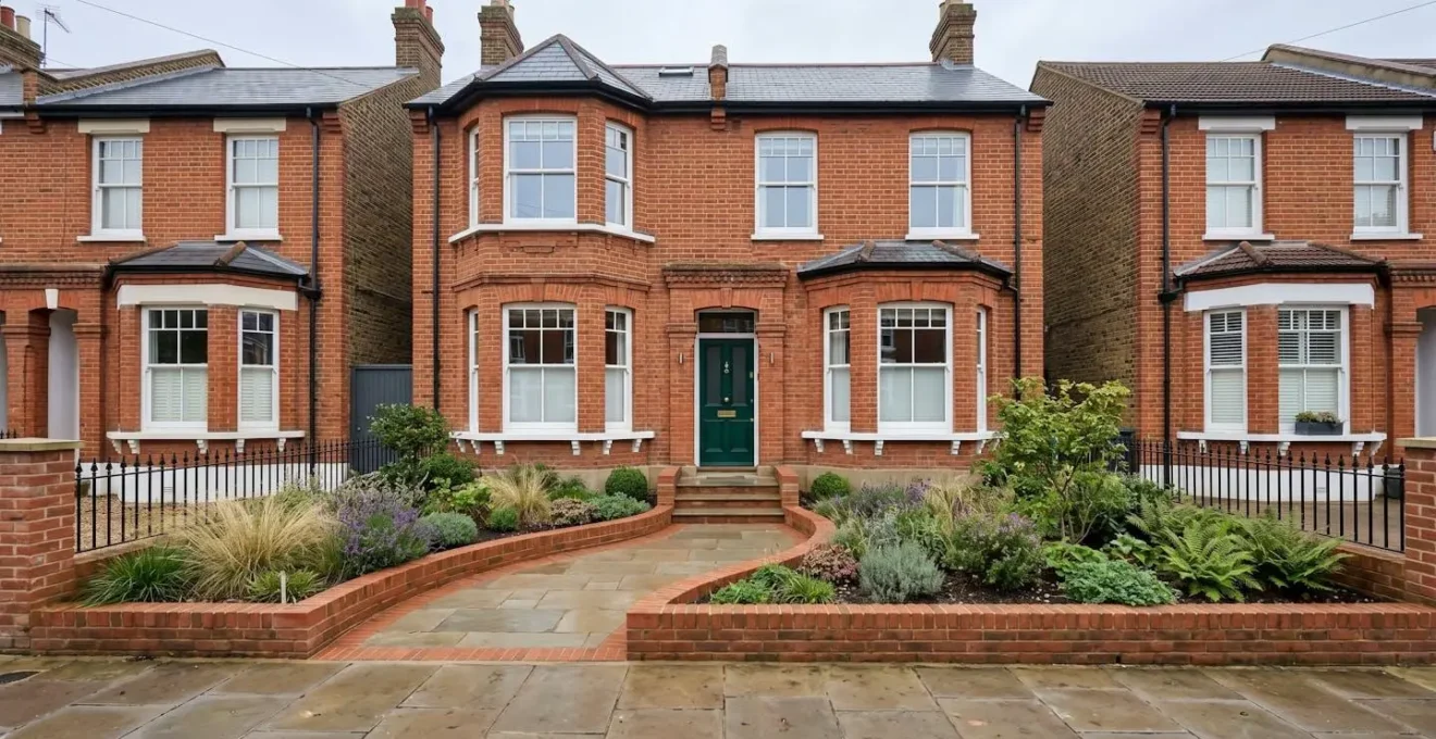
This image showcases an exemplary solution. Rather than an industrial-looking addition, the ramp is a graceful, paved path that winds through raised planters. It is constructed from materials that complement the house’s brickwork, making it feel like an original, intentional part of the design. This method addresses the practical need for access while preserving, and even enhancing, the property’s kerb appeal. For terraced properties, it is also crucial to consider the Party Wall Act 1996, as foundation work for the ramp may affect the shared boundary with a neighbour, requiring a formal agreement before work commences.
The journey to a truly open-plan and future-proofed home is one of precision, foresight, and expert collaboration. To ensure your project is built on a solid foundation, the next logical step is to engage a qualified structural engineer who can translate these principles into a bespoke plan for your property.